 Happy Egg Farm
Pastured-chicken keepers know that chickens will normally return to a coop to sleep, and since many of their predators are nocturnal, we can keep them safe by simply closing the door to their coop. Manually closing a door each night and opening that door the next morning may sound fine to someone who is used to keeping dogs, but we are cat people, and not really interested in that sort of commitment.
The alternative is some sort of motorized coop door on a timer or daylight sensor. These days there are several to choose from, but a few years ago when we first started looking for a system, there was really only one viable option, the VSB system from Europe. We used that system as-delivered with a mechanical timer for a few years, and it worked out well.
The actuator system is contained in a single rain-proof plastic enclosure with a transparent cover. The components in that box operate on four AA alkaline batteries. The door motion comes from a small geared motor that winds a very durable thread/string around an axle. The motor/gearbox is mounted to a circuit board that features a light sensor, a potentiometer for adjusting the light sensor, input pins for an external light sensor or timer, and limit switches.
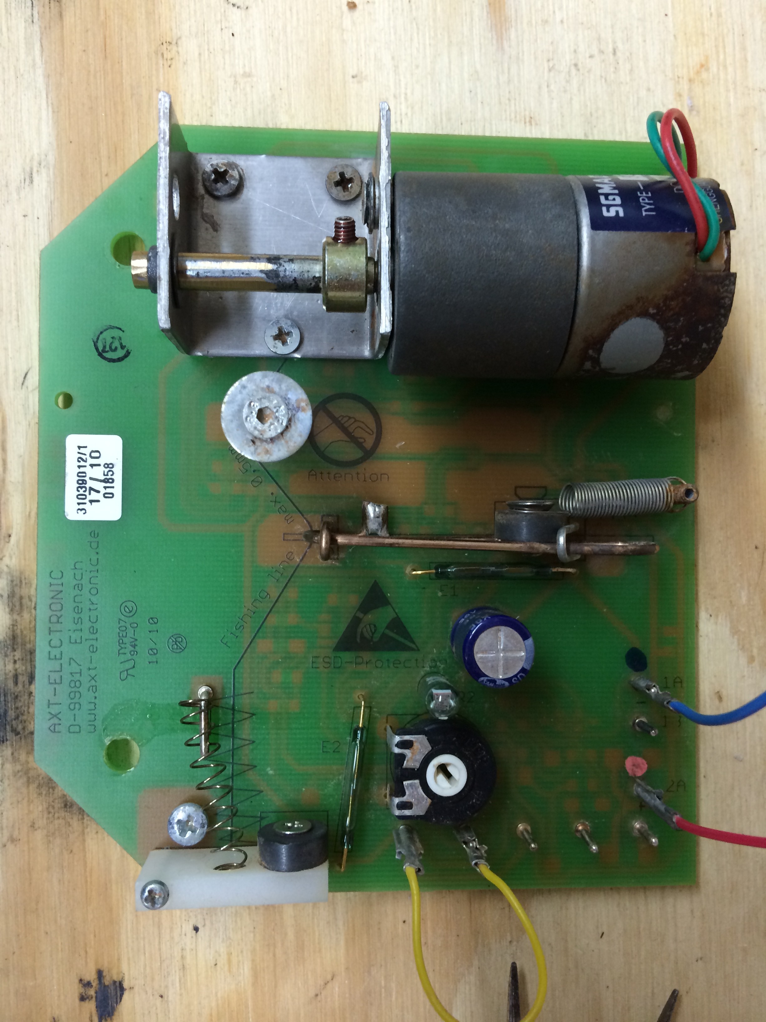
The design is very clever. Instead of using mechanical limit switches that would wear out and be susceptible to environmental challenges in the coop, the system uses non-contact reed switches that are operated by magnets. These are visible in the photo running vertically just to the right of the pivoting plastic arm on the lower left, and running horizontally between the sliding switch in the middle of the board and the large blue capacitor.
The connections on the lower right corner are as follows. Pins 1a and 1b are electrically common, and go to the negative side of the supply voltage at the AA batteries. Pins 2a and 2b are also electrically common with each other and go to the positive side of the AA batteries. The remaining pins across the bottom are referred to in the instructions as 3, 4, 5, and 6. In the photo, 5 and 6 are shorted with a yellow jumper. This jumper causes the circuitry to bypass the optical sensor (located just below and to the left of the blue capacitor, and just above the potentiometer. The potentiometer is where one would adjust the light sensor, and as I understand it, pins 5 and 6 could also connect to a remote light sensor. When the circuit is closed, then the door is closed.
Pins 3 and 4 are connected to the timer in our setup, though in the photo they aren’t connected to anything. When those pins are shorted, the door will close. When the system is in “door closed” mode, the motor will unwind the string until the sliding switch in the center of the board slides to the right. This is an indication to the logic that the door is now resting on the bottom of its track, since the string is slack. In door open mode, the motor winds up the string until a knot in the string hangs up in the small hole in the piece of white plastic on the lower left side of the board. When that knot hangs up in the small hole, the plastic arm lifts, and the magnet opens the reed switch.
Our opener worked well for the first few years. We would have to periodically adjust the timer to account for seasonal changes in the length of the day, but that was to be expected. The batteries lasted a long time- at least several months, and perhaps a year at times. It was slightly inconvenient that the two systems used different batteries, but not a big deal.
All of that worked well until our big flood in the summer of 2013. The system was submerged while powered for some time, and I didn’t have any expectations for it to work again. I removed the expensive parts from our wrecked chicken coop and tossed them in a cardboard box for over a year, when our new chicken house was ready for a door actuator.
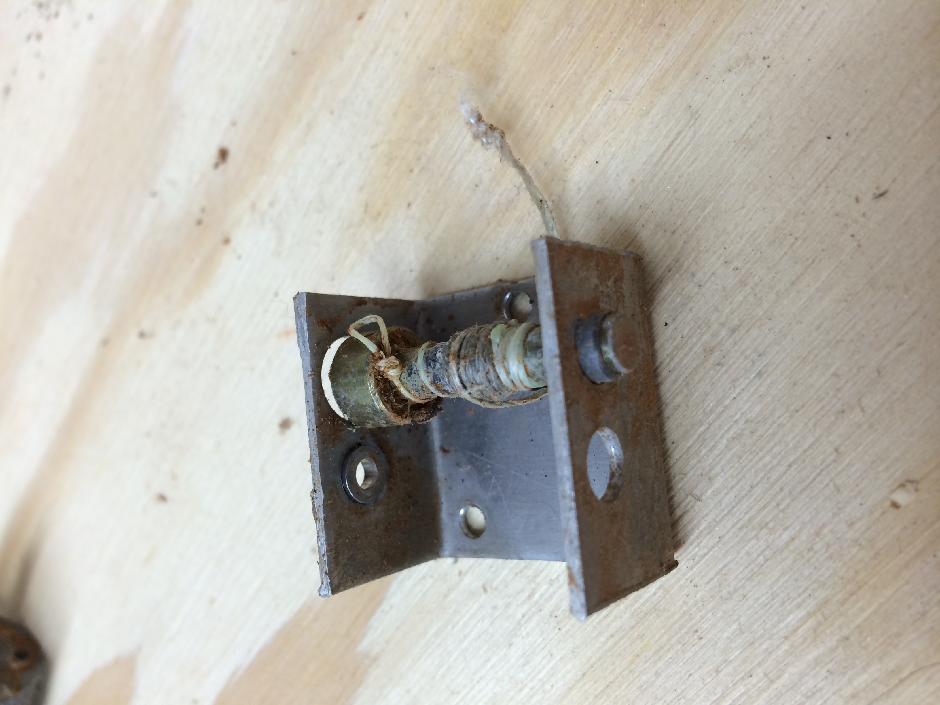
The circuit board is potted with some sort of clear varnish, so I had hopes that maybe the circuitry was OK. I removed the motor from the board and took apart the gearbox, cleaning each gear and packing with fresh grease. I cleaned and lubricated the motor, which seemed fine.
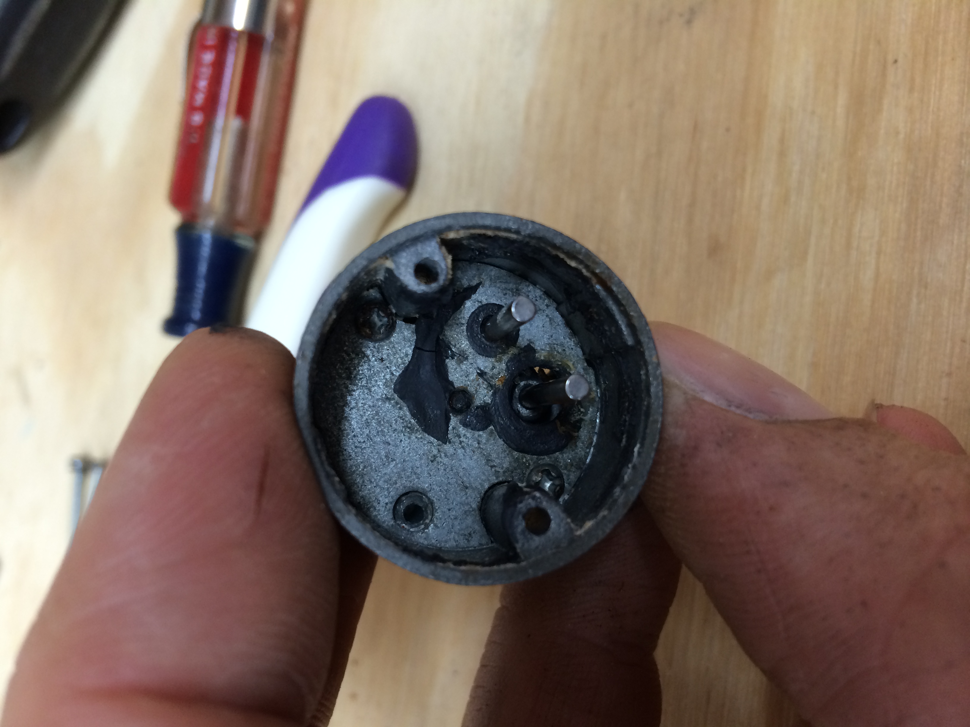

With 6 volts applied to the motor leads directly, it worked great. But when I reconnected the motor to the circuit board, I couldn’t get it to work. There was probably some water damage to the circuitry after all, which is certainly not a surprise considering the exposure. I wrote to the manufacturer in Germany to see if they could suggest any further troubleshooting or if they could supply any parts, and they offered to send a new circuit board and motor for $65 with shipping. This was an appealing option, since the new system all together would have cost closer to $200, and I really only needed the board itself. Since I was starting fresh with the new chicken house, I decided to make a few changes to the door opening arrangement, and I’ve made another entry to describe those changes here.
Proudly powered by WordPress.
Theme: Flat by YoArts.